
Digital Exclusive: Carbon critical—How filtration adds value in CCUS systems
C. JOY, Cleanova, Killarney, Ireland
The decarbonization of industrial activities is key to mitigating climate change. From power generation to transportation to food production, there is a clear imperative to reduce the amount of carbon dioxide (CO2) entering the atmosphere. Techniques for separating CO2 from gas streams are well-established, but the sustainability imperative is presenting new challenges for everyone involved.
The scale of the decarbonization challenge is daunting. Countries around the world signed the Paris Agreement in 2015, committing to limit global temperature rise to well below 2°C above pre-industrial levels.1 Achieving this target requires aggressive decarbonization efforts. Estimates suggest that between 350 gigatonnes (Gt) and 1,200 Gt of CO₂ must be captured and stored this century. Currently, only some 40 megatonnes (Mt) of CO₂ are captured and stored annually, so capacity must increase at least 100-fold by 2050 to meet the necessary targets.2 The development and deployment of carbon capture, utilization and storage (CCUS) technologies at scale is therefore a key imperative.
CCUS encompasses a suite of technologies designed to capture CO₂ emissions from point sources such as power plants and industrial facilities, preventing their release into the atmosphere. The captured CO₂ can then be processed for storage underground or repurposed for industrial use. Whatever the final application, filtration plays a critical role at every stage: from initial capture to compression, transportation, and storage or reuse.
Storage or utilization? Arguably, the biggest question for society and industry is what to do with all that carbon once it is captured. As any filtration expert will state, it is the desired outcome that drives effective system design.
The practical challenges of permanent CO₂ storage are considerable. Identifying and assessing potential storage sites can be time-consuming and expensive. Where appropriate geological sites are identified, they may need to be adapted and monitored continuously. This includes installations using significant volumes of CO2 injected underground as part of conventional enhance oil recovery (EOR) operations. That said, proximity to suitable sequestration locations is likely the biggest global impediment to CO2 storage. Transportation distances can range from considerable to impractical. Building, monitoring and maintaining the necessary infrastructure adds significant costs.3 For carbon capture to become viable at scale, storage is unlikely to present the most economical or practical long-term solution.
Utilization can be a better option. Applying circular economy principles and reusing CO2 in other industrial processes clearly supports the spirit and intent of the Paris Agreement by making CCUS more sustainable. Additionally, there are established markets for CO2, including carbonated drinks, food packaging and fire suppression, as well as emerging markets such as the production of eFuels. Crucially, this means that captured CO2 becomes a value stream rather than a financial burden for carbon-intensive industries.4
Whether you are designing a carbon capture system for storage or utilization, the quality of the captured CO₂ is critical for success—this is where filtration comes into its own. Filtration not only removes contaminants to deliver the desired final product quality, but it also protects processing equipment and improves operational efficiency.
More details of how filtration is applied in the different phases of carbon capture, as defined by the National Energy Technology Laboratory (NETL),5 are presented in the following sections.
FILTRATION DURING CAPTURE
CCUS projects primarily focus on capturing CO₂ emissions from point sources. Presently, it is more cost-effective to capture the gas directly from concentrated exhaust streams rather than from the ambient air. Correctly applied, filtration maintains carbon capture system efficiency and delivers the CO2 to downstream processes with minimal contamination.
Post-combustion filtration. Chemical absorption is the most mature technology for post-combustion capture. This process uses solvents (e.g., amines) to selectively absorb CO₂ from the flue gas. It is commonly deployed in power plants, cement production and other industries that burn hydrocarbons to produce energy. The CO₂-laden solvent is heated to release the captured CO₂, which is then compressed for transportation or storage.
FIG. 1 illustrates the primary points where filtration should be applied in a solvent absorption system. It is important to prevent any contamination reaching the top of the absorber column because it will directly impact the quality of the CO2 and may lead to inefficient CO2 capture. High-capacity particulate filters are applied to remove contaminants from both feed gas and downstream processes. Coalescers protect the solvent from impurities in the flue gas that can cause fouling, foaming and solvent degradation—phenomena that result in a lower per unit CO2 capture rate and exhausted CO2 escaping into the atmosphere. Activated carbon filtration is important in removing residual organics and hydrocarbons for much the same reasons. Oil mist eliminators ensure that only clean and oil-free air is exhausted by rotating equipment, in compliance with air quality standards.
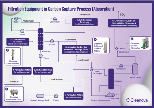
FIG. 1. Filtration equipment in the absorption carbon capture process.
Pre-combustion capture. CO₂ can also be separated from the fuel before combustion occurs using the pre-combustion capture method. This technique is commonly used in integrated gasification combined-cycle (IGCC) plants, where fossil fuels are converted into syngas [a mixture of carbon monoxide (CO), hydrogen (H2) and CO₂]. The CO reacts with steam in a process known as the phase shift reaction, which increases the concentration of H2 and CO₂ in the gas mixture. The CO₂ is then separated, allowing the H2 to be used as a clean fuel.
Pre-combustion capture requires filtration to remove impurities such as sulfur compounds, particulates and moisture from the syngas before CO₂ separation. Membrane technologies, pressure swing adsorption (PSA) and solid sorbents are often used for CO₂ removal in pre-combustion systems.
Oxy-combustion capture. Oxy-combustion involves burning fossil fuels in an environment of pure oxygen (O₂) instead of air. This reduces the presence of nitrogen in the flue gas, leaving primarily CO₂ and water vapor as combustion byproducts. The water vapor can be easily condensed, leaving a highly concentrated stream of CO₂.
The key component of an oxy-combustion system is the air separation unit (ASU), which generates the pure O₂ required. Filters are essential for removing impurities from the incoming air to protect the ASU and ensure efficient oxygen production.
Direct air capture (DAC). DAC is a relatively new technique. This non-combustion form of carbon capture enables CO2 to be removed directly from atmospheric air. Solid DAC relies on sorbent materials with an affinity towards CO2 and uses a cycle system of adsorption and desorption. Liquid DAC uses solvents in a process based on absorption and regeneration loops.
The similarities between DAC and conventional carbon capture methods facilitate the transfer of existing filtration technologies into DAC processes for filtering the incoming air, maintaining solvent purity and removing residual liquids before the air is released back into the atmosphere.
The ‘supercritical’ phase. After CO₂ has been captured, it is dehydrated and compressed to high pressure for transport and storage. This is known as the ‘supercritical’ or ‘dense phase’ state. Filtration is essential for efficiency and safety during this process.
Contaminants such as water, lube oil, O2 and hydrogen sulphide (H₂S) present in the CO₂ can threaten pipeline integrity by causing corrosion or pipeline blockages. Solid corrosion products and pipe scale can also be carried downstream, fouling critical equipment such as control valves, metering stations and high-pressure injection pumps. This increases maintenance costs and can involve equipment replacement or unscheduled downtime. Solid contaminants can also plug permeable storage reservoir pore structures, requiring increased energy for CO₂ injection and limiting the amount of available reservoir storage capacity.
FIG. 2 illustrates where filtration should be applied during the supercritical phase. In selecting filters and separators for dense phase CO₂ applications, substantial care must be taken over which materials are used, how filter sizing is performed and the correct filtration rating. To protect reservoirs, the filter rating must be selected based on the reservoir permeability and approximate pore diameter.
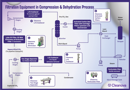
FIG. 2. Filtration equipment in the CO2 compression and dehydration process.
Advances in CCUS filtration. While on a rapid development track, the CCUS sector is far from mature and focused primarily on finding and developing new CCUS technologies and materials. The challenge for filtration specialists is to leverage the proven benefits of technologies that have been used reliably for many years in conventional natural gas applications and redesign these to meet the requirements of CCUS applications.
One example of success is the author’s company’s filter technologya, which has been developed to address the problems that arise in absorption-based CCUS systems where high levels of particulate contaminants can impede the effectiveness of the amine and lead to clogging of downstream process equipment. These filtersa provide a market-leading solid removal capacity per unit area and are configurable across a wide range of filtration efficiencies (1 µ–100 µ).
The company’s filter technologya is absolute rated and tailored to protect a range of physical solvent processes, including monoethanolamine and diethanolamine (MEA/DEA), a proprietary solventb and a proprietary solvent processc, which are currently gaining traction for pre-combustion carbon capture. In parallel, the company’s filtration is highly effective in high-pressure supercritical CO2 injection applications where low particle concentrations are critical to the efficient sequestration of the gas in depleted rock formations.
However, better filtration equipment alone will not solve the challenges of decarbonizing industrial processes using CCUS. No ‘standard’ design for CCUS exists and each application will have unique process challenges. Identifying the best filtration solution, therefore, requires system designers and filtration experts to work together in a new way. The author’s company provides a solution, both in terms of market-leading filtration products and access to a global pool of engineering and process expertise.6 This innovative approach recognizes that each process has unique parameters and each customer has specific needs and desired outcomes.
The company provides tailored filtration solutions designed for each carbon capture process, based on the chosen method, load quantities, type of contaminants, CO2 concentration, pressure and temperature. The aim is to collaborate with CCUS operators from the earliest concept stages, because considering filtration requirements from the outset—and within the context of the entire system design and business model—will yield the best results.
Takeaways. The successful adaptation of existing technologies such as filtration to meet the specific requirements of CCUS operations is an ongoing process, and early collaboration is crucial to the success of any decarbonization journey.
The company is actively developing partnerships with new process developers and licensors to ensure that new product development meets CCUS developments now and in the future. Its pioneering approach is already delivering technological results and encouraging better business practices. The company is exploring how filtration can evolve to meet the needs of new technologies like DAC and bioenergy with carbon capture and storage (BECCS).7
NOTES
a Cleanova’s UNIQ-MAX
b Dow’s Selexol™
c Air Liquide’s Purisol
LITERATURE CITED
1 United Nations Climate Change, “The Paris Agreement exhibit,” online: The Paris Agreement Exhibit | UNFCCC
2 Page, B., “Carbon capture and storage can help us beat climate change,” Global CCS Institute, December 2, 2020, online: Carbon capture and storage can help us beat climate change | World Economic Forum
3 SolartronISA/AMETEK, “Challenges of CCS,” online: Challenges Of CCS
4 Tiwari, S., K. S. Mohammed, G. Mentel, S. Majewski and I. Shahzadi, “Role of circular economy, energy transition, environmental policy stringency, and supply chain pressure on CO2 emissions in emerging economies,” Geoscience Frontiers, Vol. 12, Iss. 2, May 2024, online: Role of circular economy, energy transition, environmental policy stringency, and supply chain pressure on CO2 emissions in emerging economies - ScienceDirect
5 National Energy Technology Laboratory, “(9.2.) Carbon dioxide capture approaches,” online: 9.2. Carbon Dioxide Capture Approaches | netl.doe.gov
6 Cleanova, “Cleanova.C-CLEAN: Transitioning to net zero with CCUS,” online: Cleanova.C-CLEAN - Cleanova Filtration Solutions for Industry
7 Cleanova, “Carbon capture, utilization and storage: A filtration perspective,” online: Whitepaper: Carbon Capture Utilisation and Storage (CCUS) - A Filtration Perspective - Cleanova Filtration Solutions for Industry
ABOUT THE AUTHOR
Colm Joy is the Chief Technical Officer at Cleanova and has more than 25 yrs of experience in filtration product design, process development and industrial plant filtration applications. His role involves overseeing the development and performance of Cleanova’s filtration portfolio, which includes brands such as Airpel, Allied, Dollinger, Plenty, Shawndra, Sidco and Vokes. Among his achievements is the design of Cleanova’s onsite gas filtration test solutions, which give customers greater insight into their gas process and filtration requirements. He is passionate about filtration’s role in delivering more sustainable operations, improving product quality, overall equipment effectiveness (OEE) and total cost of ownership (TCO). Joy holds a degree in mechanical engineering and an MS degree in manufacturing and structural engineering.

Related News
Related News

- Mitsubishi Heavy Industries Compressor acquires Swiss rotating equipment maintenance company AST Turbo AG
- RWE strengthens partnerships with ADNOC and Masdar to enhance energy security in Germany and Europe
- TotalEnergies and Mozambique announce the full restart of the $20-B Mozambique LNG project
- Cook Inlet LNG advances FSRU project in Alaska (U.S.)
- Qatar’s Ras Laffan LNG hub hit by missile attack, ‘extensive damage’ reported

Comments